
Precision turned components often control fit, motion, sealing and alignment within a larger assembly. Small variation in diameter, concentricity, runout or surface condition can influence the performance of the entire product.
At Tianyida, each project begins with an engineering review of the geometry, material, tolerances, functional interfaces and production quantity. This allows us to select a practical turning or turn-mill strategy and define inspection around the characteristics that matter most.
A precision component is not defined only by its dimensions, but by how reliably it fits, rotates, guides, seals or connects after assembly.
Shafts, spindles, rollers and journals manufactured for controlled rotation, fit and surface interaction.
Bushings, sleeves, locating pins and spacers designed for alignment and repeatable assembly.
Adapters, fittings, nozzles, threaded bodies and interfaces where threads and sealing surfaces affect performance
Seats, shoulders and related diameters requiring controlled fit, runout and positional relationships.
Rotational bodies with bolt patterns, bores, faces and assembly features that may require turning and milling.
Components combining rotational geometry with flats, slots, cross holes or off-axis features to reduce secondary setups
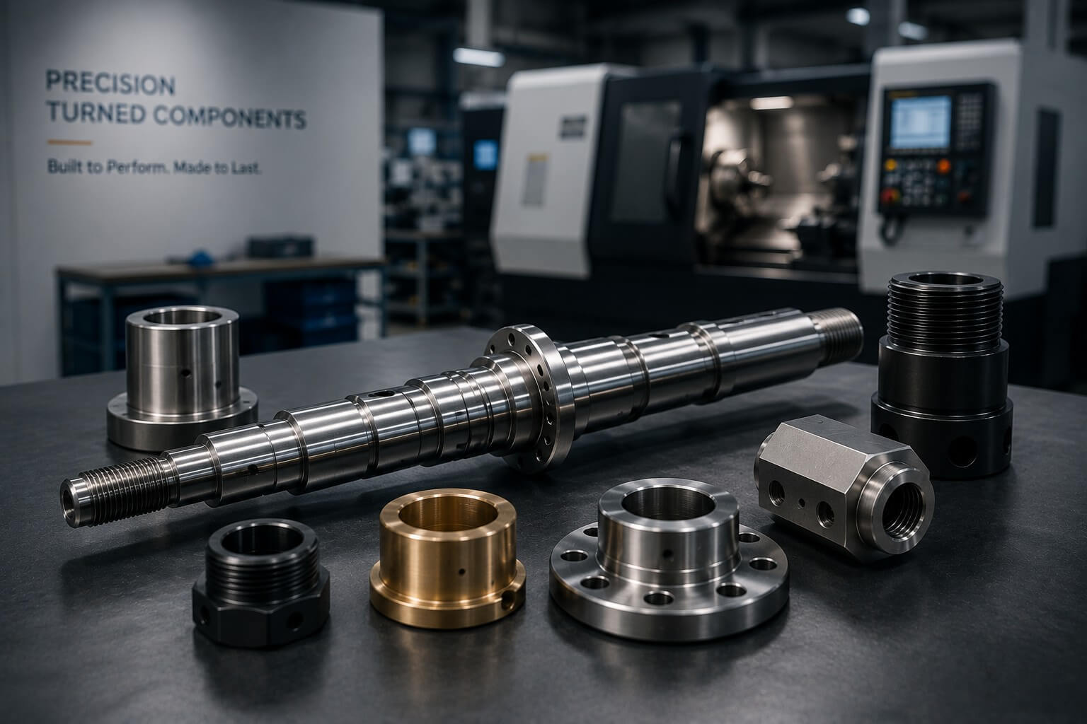
Understanding the part’s function helps determine which diameters, shoulders, threads, bores and surfaces require the greatest process control. It also helps avoid treating every drawing requirement as if it creates the same manufacturing risk. Our engineering team reviews how related features work together so that machining and inspection decisions support the final assembly—not only an isolated measurement.
The right process depends on geometry, feature access, tolerance relationships, material and production quantity—not machine preference.
Diameters, shoulders, tapers, grooves and profiles machined according to functional and dimensional requirements
Bores, counterbores, internal grooves and precision internal features planned around access, rigidity and measurement.
External and internal threads produced according to drawing specification, fit and gauge requirements
Controlled groove geometry and cut-off strategy with attention to burrs, deformation and surface condition.
Milling, drilling and cross-working features integrated with turning where part geometry and equipment capability permit.
Grinding, heat treatment, EDM, plating, passivation and other required operations can be coordinated by project
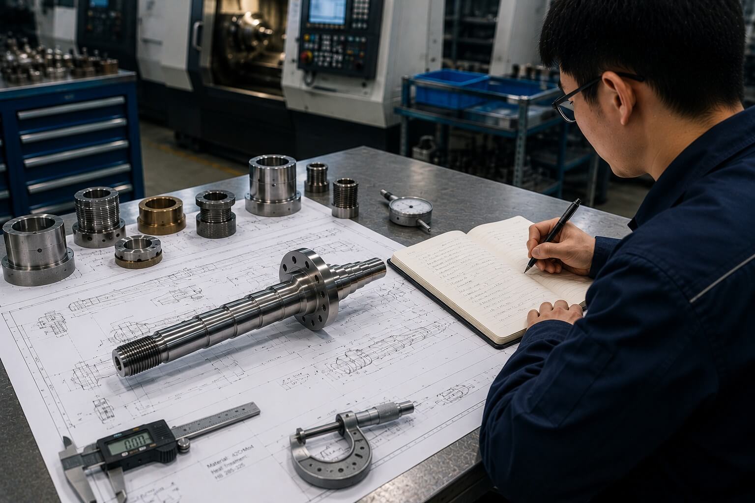
Conventional CNC turning is efficient for rotational features, while turn-mill machining can combine flats, slots, cross holes and other non-rotational details in a coordinated setup. Where appropriate, reducing reclamping helps protect the relationship between turned and milled features.
Every project is reviewed individually so that tooling, workholding, machining sequence and inspection methods support stable manufacturing without adding unnecessary complexity.
Material grade and condition influence cutting behavior, tool wear, dimensional stability, surface finish and final product life.
Used for corrosion-resistant, medical, fluid-control and industrial parts. Work hardening, heat, burr formation and passivation requirements affect process planning.
Selected for shafts, drive components and structural applications requiring strength, toughness or subsequent heat treatment.
Applied to wear-resistant and tooling components, with hardness, stock allowance and heat-treatment sequence considered in advance.
Lightweight and efficient to machine for housings, spacers, fittings and automation components; alloy and cosmetic surfaces should be specified.
Common for connectors, fittings, conductive parts and fluid components; grade affects chip control and achievable surface condition.
Titanium requires controlled heat and tool-wear management; plastics require attention to heat, deformation and dimensional stability.
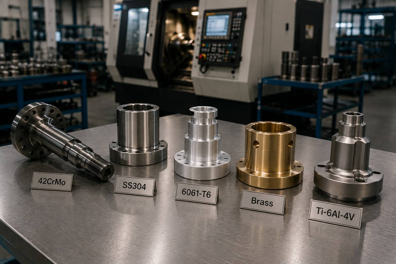
Tianyida machines common metals and engineering plastics according to customer drawings and specifications. Exact grade, condition, heat treatment and certification requirements should be confirmed during quotation.
If material selection is still open, we can discuss practical machining considerations based on application and production requirements; final material approval remains with the customer
Different geometries require different approaches to support rigidity, feature access, cycle efficiency and dimensional consistency.
Straight, stepped, tapered and threaded components with controlled diameters, shoulders and related features.
Internal and external diameters, grooves and faces produced for fit, guidance, sealing or wear interfaces.
Components combining bores, faces, diameters and bolt-pattern or milled features.
Threaded and fluid-related components requiring clean edges, sealing surfaces and reliable connections.
Rotational components requiring controlled runout, journals, surface condition and stable geometry.
Rotational parts incorporating flats, slots, holes, pockets or off-axis features in a coordinated process.
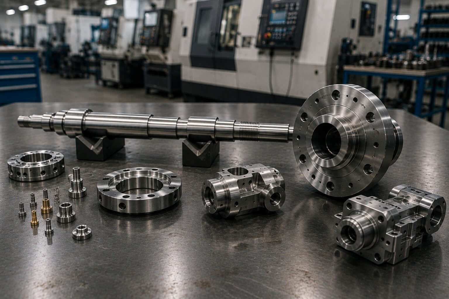
Our CNC turning capability supports a broad range of drawing-based components for prototypes, low-volume orders and repeat production. The examples below represent typical part families rather than a fixed catalogue.
Each project is evaluated for the complete route, including turning, milling features, deburring, heat treatment, finishing, inspection and packing.
Rotational performance depends on how critical diameters and faces relate to one another—not on one dimension alone.
Related diameters and bores are machined with a strategy that protects their shared axis and functional fit.
Radial and axial runout are considered for rotating surfaces, shoulders, flanges and bearing-related features.
Cutting stability, support and tool condition influence whether rotational surfaces remain consistent along their length.
Measurement method and process control are matched to clearance, transition or interference-fit requirements.
Perpendicularity, axial position and surface condition affect bearing location, sealing and assembly stack-up.
Cutting parameters, tool geometry and material behavior are managed to achieve functional surface requirements.
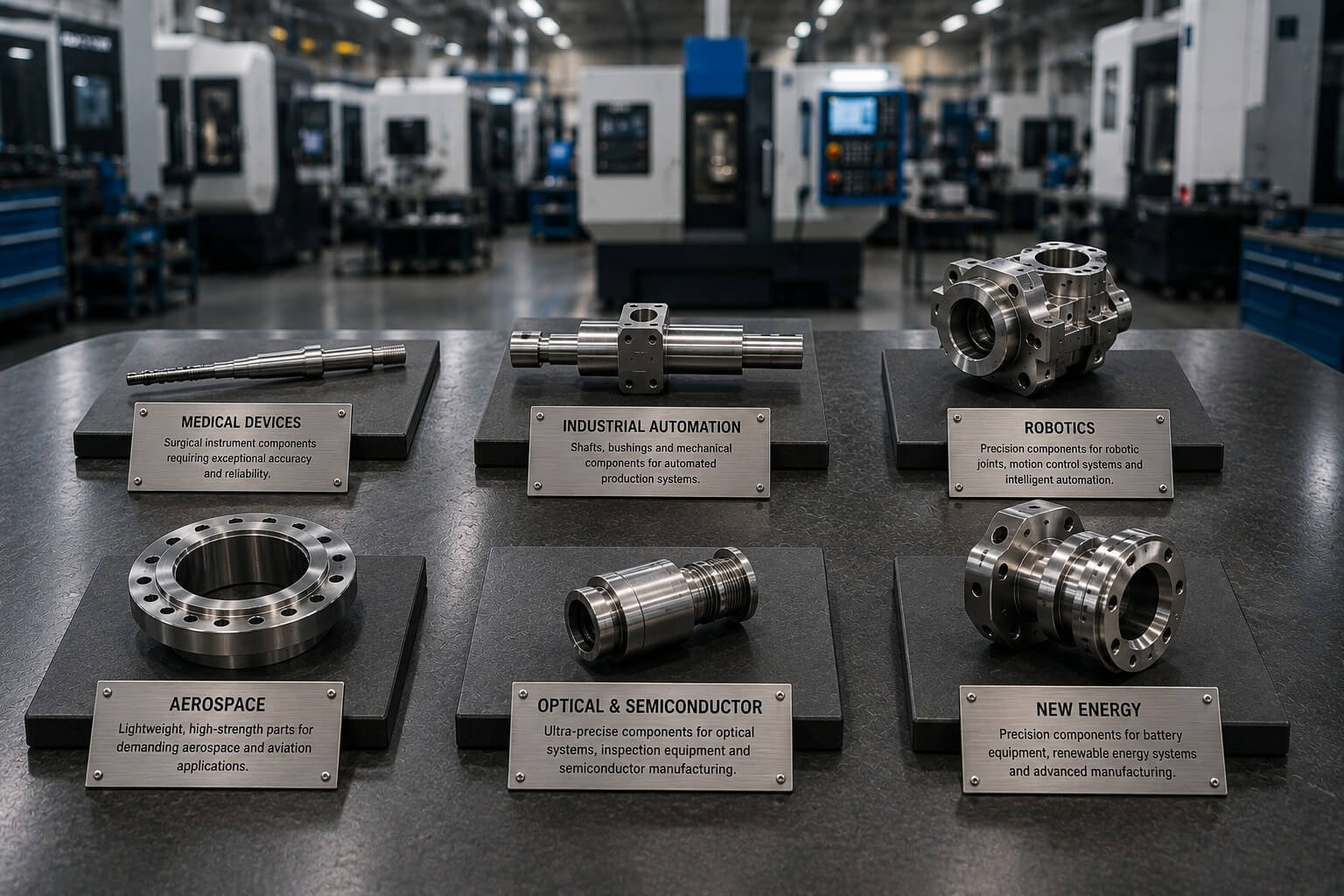
A shaft can meet its diameter tolerance and still create vibration or assembly problems if bearing seats, shoulders or mating diameters are not correctly aligned. For rotating, guiding and sealing components, geometric relationships must influence the manufacturing and inspection strategy.
Workholding, datum selection, machining sequence, tool condition and measurement method are planned according to the functional importance of each feature.
Inspection verifies the result; controlled machining is what makes that result repeatable across the order.
Current models, drawings, material, finish and acceptance requirements are confirmed for production.
Initial parts are inspected before the process is released for continued production or approval where required.
Critical diameters, lengths, threads and geometric relationships are checked during machining.
Tool condition and dimensional trends are monitored to maintain consistency as production continues.
Dimensions, runout, threads, deburring, finish and workmanship are verified using suitable equipment.
First-article, dimensional and CMM reports can be provided when requested and agreed during quotation.
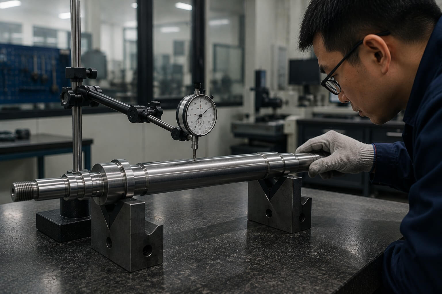
Quality control begins with the current drawing, material and agreed acceptance requirements. Critical features are identified before machining so inspection occurs at the stage where variation can be detected and corrected effectively.
Our process combines first-article verification, in-process monitoring and 100% outgoing inspection before shipment.
Reliable manufacturing means maintaining the approved level of precision as tools wear, material lots change and production quantities increase.
Workholding, tooling, programs and setup checks establish a controlled starting point for production.
Tools are monitored and replaced or adjusted according to dimensional trend and surface requirements.
Critical features are measured at planned intervals to identify variation before it affects the complete order.
Approved methods, inspection criteria and project records support repeatability across future orders.
Lessons from first articles and initial batches are incorporated into the stable production plan.
Finished parts are cleaned, separated and protected according to geometry and surface condition.
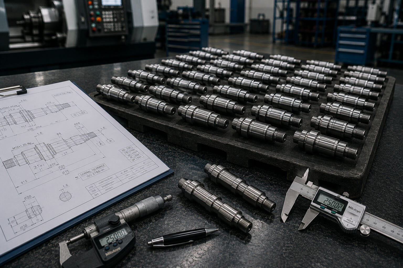
Producing one accurate sample is only the beginning. Repeat orders require standardized setups, controlled tooling, process monitoring and retained project knowledge so that future batches match the approved requirement.
The same engineering discipline is applied from prototypes and low-volume orders through stable production, with the process adjusted responsibly as quantity and manufacturing data increase.
Long shafts, thin walls, deep bores and complex features require different solutions for support, cutting forces, heat and measurement.
Support, cutting parameters and machining sequence are planned to reduce deflection, chatter and loss of straightness.
Controlled clamping, sharp tooling and balanced material removal help reduce deformation during and after machining.
Tool rigidity, chip evacuation, coolant access and measurement strategy are considered for depth and diameter.
Tooling and cutting conditions are selected for cross features, slots or geometry that interrupts continuous turning.
Heat, work hardening and tool wear are managed through suitable tooling, parameters and inspection frequency.
Machining related turned and milled features in a controlled setup can improve their positional consistency.
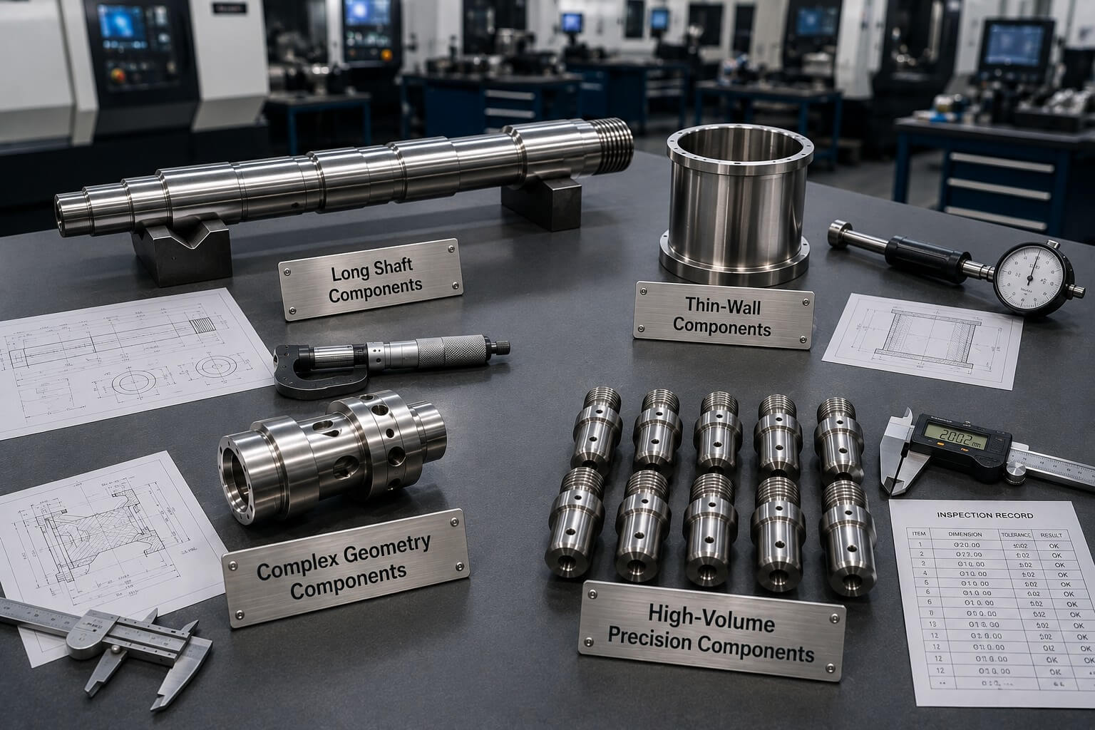
Applying one standard turning method to every geometry can lead to vibration, deformation, poor chip evacuation or inconsistent dimensions. The most effective approach begins by identifying the part’s specific risk and planning the process around it.
Our engineers evaluate workholding, support, tool access, machining sequence and inspection requirements before production begins.
Send your drawings and receive an engineering review together with a project-based quotation.
Whether you need a single prototype, a precision shaft, a complex turn-mill component or repeat production, Tianyida is ready to review the complete manufacturing requirement.
With 10 years of precision manufacturing experience, an ISO 9001:2015 quality system and support for international delivery, our Shenzhen team helps customers move from drawing review to verified production with clear communication.
STEP, STP, IGES, X_T, Parasolid or another suitable 3D format, plus a drawing showing tolerances and GD&T.;
Exact grade, heat treatment, coating, masking and
certification requirements.
Prototype quantity, batch sizes and estimated
annual demand where available.
Target date, destination, packaging, inspection
reports and special acceptance requirements.
Shenzhen Tianyida Precision Technology Co., Ltd. is a trusted precision manufacturing partner specializing in CNC machining, sheet metal fabrication, rapid prototyping, and complete manufacturing solutions.